
Introduction
CNC machine setup is one of those skills that looks straightforward until something goes wrong. A crashed tool, a scrapped first part, or a vise that wasn't properly squared — these aren't random events. They're almost always the result of skipped steps or rushed preparation.
Setup isn't a one-time installation. It's the full operational preparation required before any part can be cut, covering:
- Tooling selection and installation
- Work offsets and tool length offsets
- Workholding and part fixturing
- Program loading and verification
- Pre-run validation
Operators doing this work are typically trained in-house, following shop-defined procedures. Those procedures get shortcut for familiar reasons: the job is urgent, a step seems obvious, or the prior setup "was basically the same." When that happens, the consequences show up during the cut — scrapped parts, crashed tools, and rework that costs more than the time the shortcut was supposed to save.
This guide walks beginners through CNC machine setup in the correct sequence, from pre-setup preparation through final validation before the first part runs.
Key Takeaways
- CNC setup is a repeatable sequence — it must be completed fully for every new job or tool configuration
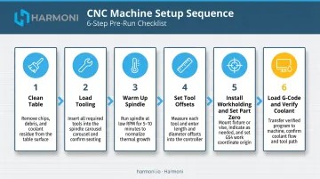
- Follow the correct order every time: clean → load tools → warm up spindle → set offsets → install workholding → set part zero → load G-code → verify coolant
- Skipping tool length offsets or part zero setup is one of the fastest routes to a tool crash
- Setup sheets and standardized checklists reduce operator error, especially on complex multi-tool jobs
- Always run a dry cycle before the first live cut — no exceptions
Before You Begin: Prerequisites and Safety
What Must Be in Place Before Setup Starts
Proceeding without the right materials staged creates mid-setup interruptions that introduce errors. Before touching the machine, confirm:
- The G-code program is finalized, approved, and the correct version is available for loading
- The job's setup sheet is on hand and current
- All required tooling, toolholders, and raw material are staged near the machine
- The machine table is clean and free of chips or coolant from the previous job
- The machine is powered on and has completed its homing cycle
Before moving on, confirm these compatibility checks as well:
- All tools on the setup sheet are available and loaded into the correct toolholders
- Workholding equipment (vise, fixture, clamps) matches the job's requirements
- The tool changer has enough open slots for the job's full tool count
With staging and compatibility confirmed, the next step is verifying that safety requirements are met before the setup physically begins.
Safety Requirements
OSHA 1910.147 covers lockout/tagout (LOTO) when setup or servicing exposes a worker to injury from unexpected energization or stored energy. Follow your shop's machine-specific energy-control procedure — a control stop or feed hold is not automatically an energy-isolating device.
OSHA 1910.132 requires a documented hazard assessment and appropriate PPE selection. During tool loading and handling, the minimum standard is safety glasses with side protection and closed-toe shoes.
Do not proceed with setup if:
- The machine has active alarms or uncleared faults
- Tool offsets from the previous job haven't been cleared or confirmed
- The machine hasn't completed a warmup when tight tolerances are required
Step-by-Step CNC Machine Setup Process
CNC setup follows a defined sequence — each step depends on the one before it. Loading a program before setting offsets, or setting part zero before workholding is secured, are common beginner mistakes that create avoidable errors downstream.
Step 1: Clean the Machine Table and Surfaces
Clear all chips, coolant residue, and debris from the machine table, fixture mounting surfaces, and vise jaws before anything else is mounted. A chip the thickness of a business card under a vise jaw will tilt your part and throw every dimension off.
Use a brush or directed air for chip clearing. Don't blast chips into the spindle, coolant lines, or way covers.
Step 2: Load and Organize Tooling
Stage tools on a tool cart in the order listed on the setup sheet. Each toolholder type has its own requirements — ER collet chucks need correct torque when tightening; BT or CAT holders require clean tapers and clean spindle interfaces.
Critical: Tool numbers loaded into the machine's tool changer positions must match the tool numbers called in the G-code program. A tool number mismatch puts the wrong cutter in the wrong operation.
Step 3: Warm Up the Machine and Spindle
CNC machines experience thermal expansion as components heat up. Running a warmup program — gradually ramping spindle speed — stabilizes the machine before critical offsets are set.
Warmup requirements vary by machine and manufacturer. Haas specifies running its warmup program after more than four days of idle time or before high-speed operation without gradual acceleration. Okuma's Thermo-Friendly machines use design-based compensation that reduces or eliminates warmup requirements. Always follow your specific machine's OEM procedure — the consequences of skipping this step show up in your first part, not your setup sheet.
Skipping warmup on jobs requiring tight tolerances risks dimensional drift during the first run.
Step 4: Set Tool Length Offsets and Diameters
Tool length offsets (TLO) tell the machine exactly how long each tool is from its reference point, so it positions the spindle correctly during cutting. This is one of the most error-prone steps in the entire process.
Three methods exist:
| Method | How It Works | Key Consideration |
|---|---|---|
| Manual touch-off | Touch each tool to a known surface, enter the length | Practical for few tools; replacement tools must be re-touched |
| On-machine touch setter | Probe measures the tool in the machine automatically | Requires calibration; consumes spindle time |
| Offline presetter | Measure assemblies outside the machine, transfer data | Prep happens while machine is running; adds data-transfer step |

Haas identifies an improper tool or work offset as one of the most common ways to crash a machine. An incorrect TLO can drive a tool into the workpiece or fixture on the very first move.
Step 5: Install Workholding and Set Part Zero
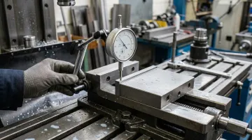
Mount the vise, fixture, or clamping setup to the clean machine table and torque all hardware to spec. If the job requires it, indicate the workholding with a dial indicator to confirm it's square to the machine's X-axis.
Then set part zero — also called the work offset or G54. This tells the machine exactly where the part's origin is in physical space, and it must match the origin defined in CAM. Get this wrong and every feature will be offset from where it belongs. Common methods include:
- Edge finder (mechanical or electronic)
- Dial indicator run along a reference edge
- 3D touch probe for faster, higher-accuracy location
Step 6: Load the G-Code Program and Verify Coolant
Transfer the correct G-code file to the machine via USB, network, or direct connection. Confirm any required subprograms or probing routines are also loaded. Double-check the program name and version number against the setup sheet.
Then check coolant before running:
- Verify concentration using a refractometer (apply the product's Brix factor per Master Fluid Solutions guidance)
- Check pH and look for signs of bacterial contamination (rancid smell is a clear indicator)
- Confirm coolant level is adequate
- Aim nozzles at the cutting zone before the first cut
Common CNC Setup Mistakes and How to Fix Them
Setup errors cause the majority of first-part failures — and three specific mistakes account for most of them.
Incorrect Tool Length Offsets
The tool cuts too deep, too shallow, or crashes into the workpiece on the first move. This usually happens because the offset was measured or entered incorrectly, the wrong tool number was loaded into the changer, or the offset wasn't updated after a tool swap.
Fix:
- Re-measure all tool lengths using the machine's touch setter or an offline presetter
- Verify tool numbers match the setup sheet
- Run a single-block dry cycle at reduced feedrate before the first live cut
Wrong Part Zero / Work Offset
The machine cuts in the wrong location — features are shifted, or the tool moves somewhere unexpected at program start. Common causes include setting part zero from the wrong reference point, selecting the wrong work offset register (G54 vs. G55), or setting Z zero incorrectly when the material surface wasn't the program origin.
Fix:
- Re-touch part zero from the correct reference datum shown on the setup sheet
- Confirm the active work offset in the program matches what's set on the machine
- Jog the tool manually to the expected start position and verify before running
Workholding Not Secure or Misaligned
The part moves during machining, or finished dimensions are consistently off on one axis even though the tool path looks correct. Vise jaws not fully tightened, a chip preventing the part from seating flat, or a vise not squared to the machine's X-axis before offsets were set are the most common culprits.
Fix:
- Re-indicate the workholding device with a dial indicator
- Re-clean vise jaws and part datum surfaces
- Re-seat and re-torque all clamping hardware
- Reset part zero before rerunning
Pro Tips for Faster, More Consistent Setups
Use Setup Sheets as the Backbone of Every Job
A well-written setup sheet documents tool numbers, toolholder specs, workholding requirements, part zero location, and the G-code file name. Shops that standardize setup documentation see fewer first-part errors and can bring new operators up to speed on a job much faster.
Digital platforms like Harmoni take this further: the platform automatically delivers the correct work instructions, setup sheets, and CNC programs directly to operators at each workcenter through a machine-side command center, removing the risk of outdated paper sheets or wrong program versions.
Build a Consistent Pre-Setup Routine
Experienced operators run through the same sequence at the start of every setup — before consulting the setup sheet:
- Clean the table and remove any debris from the previous job
- Home the machine and confirm axis positions
- Stage all required tools at the workcenter
This habit is harder to build than it sounds, but it prevents forgotten steps and reduces cognitive load during complex multi-tool jobs. Consistent routines also make setup sheets more effective, since operators aren't mentally juggling what comes first.
Document Every Deviation
If a tool is substituted, an offset is adjusted, or a workholding method changes from what the setup sheet specifies, that change needs to be recorded. Undocumented deviations make troubleshooting first-part failures nearly impossible.
In regulated industries like aerospace, defense, and medical device manufacturing, the stakes are higher. Traceability gaps don't just complicate root cause analysis — they can trigger compliance findings that affect contracts and certifications.
Conclusion
Setup quality determines whether the first part comes off the machine correctly. Errors in offsets, workholding, or program loading don't announce themselves: they show up during the cut, by which point a tool, a part, or in bad cases a machine spindle may already be damaged.
Treat setup as a disciplined process. The operators who consistently produce good first parts aren't lucky — they follow a repeatable routine every time:
- Follow the setup sequence without skipping steps
- Use a setup sheet or checklist on every job
- Run a dry cycle before the first live cut
- Learn tool offset measurement and part zero location properly
These habits are what separate reliable first-part results from costly trial and error.
Frequently Asked Questions
What is a machine setup?
Machine setup is the process of preparing a CNC machine to run a specific part — loading the correct tools, setting tool length offsets and part zero, installing workholding, and loading the G-code program. It must be completed correctly before any cutting begins.
What is machine setup cost?
Setup cost is the labor and time required to prepare a machine for a job — operator time, tooling preparation, and any scrap from first-part validation. Modern Machine Shop defines setup time as the interval from the last good piece of one run to the first acceptable piece of the next; tracking that interval separately from run time is how shops build accurate job cost data.
What is a CNC setup sheet and why is it important?
A CNC setup sheet is a job-specific document listing required tools, tool numbers, workholding methods, part zero location, and the G-code file name. It standardizes setup across operators and shifts — especially critical when jobs repeat or move between machinists.
How long does CNC machine setup typically take?
Setup time varies widely by job complexity, tool count, and operator experience. Simple jobs may take 15–30 minutes; complex multi-tool setups with multiple fixturings can run several hours. One real-world data point: Gardner's 2024 Top Shops survey reported Art Metals Group averaging 240 minutes per setup, measured last-good-piece to first-acceptable-piece.
What happens if tool length offsets are set incorrectly?
Incorrect tool length offsets cause the tool to cut at the wrong depth, producing out-of-tolerance parts — or in severe cases, crashing into the workpiece or fixture on the first move. Haas lists improper tool and work offsets among the most common causes of machine crashes, which can damage the tool, part, and spindle.
What is part zero in CNC machining?
Part zero (also called the work offset or program origin) is the physical point on or near the workpiece that corresponds to the 0,0,0 coordinate in the G-code program. It must be set correctly on the machine so every tool movement matches the intended toolpath from CAM — set it from the wrong reference point, and every feature on the part will be in the wrong location.